How to Use a Wire Feed Welder
A wire feed welder can turn a pile of steel into a sturdy repair, but good results depend on more than pulling the trigger. Wire type, voltage, feed speed, material thickness, and joint preparation all shape the bead. A clean, dry surface matters. So does a stable workpiece. Even small setup errors can leave spatter, gaps, or uneven penetration.
Welding educator Jody Collier’s practical approach can be paraphrased this way: “A sound weld begins with preparation and consistent technique.” Treat that as a working principle, not a magic setting. Before striking an arc, check the machine manual, confirm the wire and polarity, and wear suitable eye, hand, and body protection. Ventilation matters, too. Welding fumes are not something to ignore.
This guide explains how to set up a wire feed welder, choose suitable starting settings, and practice controlled travel on scrap metal. You will learn what to watch for in the sound of the arc and the shape of the bead. A steady crackle can help, but it cannot replace inspection. Pause when the wire stubs, the arc sputters, or the weld looks inconsistent. Adjust one variable at a time. That is slower, perhaps, but it makes mistakes easier to understand. My advice? Expect a few rough beads. Even careful beginners need practice before their hands settle.
Identify the Process and Match Wire, Shielding Gas, and Polarity (DCEP for Solid GMAW Wire)
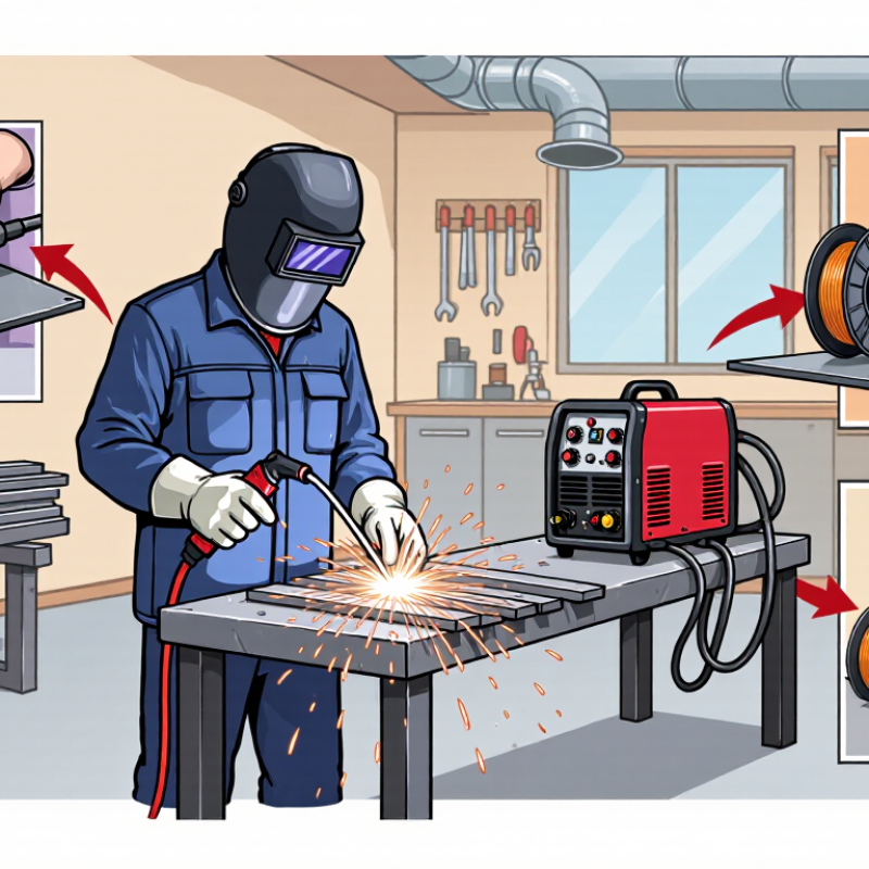
Before loading wire, identify the process: a wire-feed machine may run gas metal arc welding (GMAW) or flux-cored arc welding (FCAW). The spool label matters. Solid steel wire generally needs shielding gas; self-shielded flux-cored wire does not. Gas-shielded flux-cored wire does. For common solid-wire GMAW on steel, a 75% argon, 25% carbon dioxide blend is one option, but the wire specification and welding procedure should guide the choice. Check the machine chart, wire label, and work instructions. They should agree.
Match polarity, too. Solid GMAW wire commonly uses direct-current electrode positive (DCEP): the wire electrode is positive, and the work clamp is negative. Flux-cored wires may call for DCEP or DCEN, depending on the classification, so do not assume the settings transfer. AWS A5.18/A5.18M specifies carbon-steel GMAW electrodes, while the AWS Welding Handbook explains process fundamentals. A short test bead on clean scrap can reveal rough feeding, excessive spatter, or poor fusion. I still double-check polarity; it is easy to overlook. AWS’s 2023 workforce outlook estimated that 360,000 welding professionals would be needed by 2027, underscoring why sound setup habits matter. A number cannot replace procedure-specific guidance.
Prepare the Workpiece and PPE Under OSHA 29 CFR 1910.252
Before striking an arc, inspect the workpiece and the area around it. Remove oil, rust, paint, and moisture where practical; coatings can produce hazardous fumes. Keep the joint dry. Check both sides of the material, not just the weld face. OSHA 29 CFR 1910.252 addresses fire prevention, ventilation, and protection during welding work. Move combustible materials at least 35 feet away when possible. If they cannot be moved, shield them from sparks and hot metal. Look for gaps where sparks could fall, such as floor openings or spaces behind a bench. A fire watch may be needed when fire hazards remain.
Wear a welding helmet with a suitable filter lens, safety glasses underneath, and dry welding gloves. Cover exposed skin with flame-resistant clothing; cuffs and pockets can catch sparks. Use hearing protection when the surrounding noise or task requires it. Screens can help protect nearby workers from arc radiation, but they do not replace personal protective equipment. Check the worksite’s hazard assessment for ventilation or respiratory needs, especially when coatings or confined spaces are involved. Keep the work area clear of trip hazards, and make sure the welder’s cables and connections are in sound condition. One small oversight is easy to make: a rag tucked beneath the table can smolder unnoticed. Recheck the area before welding begins.
Wire-Feed Welding: Minimum Filter Lens Shade by Amperage
OSHA 29 CFR 1910.252 Table E-1 lists minimum protective filter lens shades for gas metal-arc welding (GMAW) and flux cored-arc welding (FCAW).
Before welding: Clean and secure the workpiece, and check the work area for combustibles. OSHA requires combustibles within 35 feet to be removed or suitably protected. Use appropriate eye, face, hand, and body protection; select a darker lens if needed for comfort. Where a fire watch is required, continue it for at least 30 minutes after welding ends. See 29 CFR 1910.252(a)(2) and Table E-1.
Load the Spool, Align the Drive Rolls, and Thread the Wire
How to Use a Wire Feed Welder
Load the spool with the wire feeding from the bottom toward the drive rolls, following the machine’s feed diagram. Check the spool turns freely, then secure its retainer without overtightening. Choose the drive-roll groove that matches the wire diameter and type. A groove that is too large can let the wire slip; one that is too small may flatten it. Align the rolls so the wire passes straight through the inlet guide and liner. I still pause here to check the path—small misalignments can cause frustrating feed problems.
Release the tension arm, feed the wire through the guides, and into the liner by hand. Close the arm, then set tension only high enough to feed steadily. Trim the wire end cleanly, keep your hands clear of moving rolls, and use the machine’s threading procedure. The American Welding Society’s workforce outlook estimated a need for 360,000 welding professionals by 2027, underscoring why sound setup skills matter across the trade.
Tips: Remove sharp kinks before threading. If the wire bird-nests, stop the feed, release tension, and inspect the inlet guide, liner, and roll alignment. Don’t just crank up tension; that can hide the real problem.
Set Voltage and Wire-Feed Speed from the WPS; 0.030-in Wire Is Common
A wire-feed welder works best when voltage and wire-feed speed match the Welding Procedure Specification (WPS). Read the WPS for the required material thickness, wire type, shielding gas, and welding position. Then set the machine to its specified voltage and feed speed. Do not treat a machine chart as a replacement for the procedure; charts are starting points, not job requirements.
A 0.030-inch wire is common for general light- and medium-gauge work, but it is not right for every setup. Check that the feeder rollers and contact tip suit the wire diameter, and keep the wire path clean. On a scrap piece of matching metal, listen for a steady arc and inspect the bead for consistent width and fusion. Small changes matter. Adjust only one setting at a time, and compare each test with the WPS. A bead can look tidy yet still have poor fusion, so appearance alone is not proof. I have found that rushing the test often creates more guesswork later. Keep notes on settings and results, especially when changing material thickness or joint position.
Run a Test Bead and Inspect Fusion, Profile, and Porosity
Before welding the job, make a short test bead on clean scrap of the same thickness and material. Keep the gun angle, wire stickout, and travel speed close to your planned setup. Watch the puddle, not just the arc. A steady sound helps, but it does not prove a sound weld. Let the coupon cool, then inspect it under bright light. Look for even width, smooth toe transitions, and a modest crown. A bead that is tall and narrow may signal poor wetting; a flat, wide bead can point to excessive heat or slow travel. Small details matter.
Check both toes for visible gaps, overlap, and undercut, then look for pinholes or clustered pores. Porosity may indicate contamination, poor shielding, or drafts; clean the test area and check gas flow before changing several settings at once. Surface appearance cannot confirm internal fusion, so cut and etch a sample when the joint’s risk or procedure requires it. The American Welding Society’s Welding Handbook describes visual examination as a key inspection method, while noting that other methods may be needed to reveal hidden discontinuities. ISO 5817:2023 organizes weld imperfections into three quality levels—B, C, and D—with B the most stringent. Acceptance depends on the applicable specification, not personal preference. Be honest about the limits of a quick visual check.